SurveyXL Window
❖You can work with building surfaces etc from the Survey window itself, or from the SurveyXL window. In this example I will access these features from the SurveyXL window. Click on Surfaces.

❖You can load spatial data into your graphics where you can build your surface from. Click on the Open icon, browse to your file and click Open. (SurveyXL supports almost all spatial data formats)
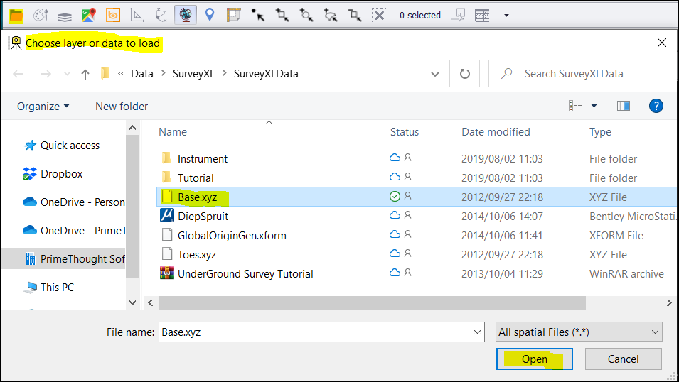
❖I have loaded an XYZ File in this example.
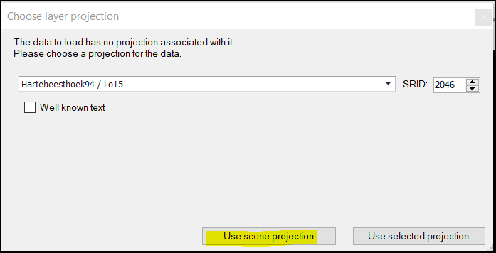
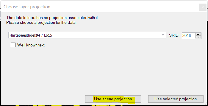
❖You will be prompted on what projection to use. Click Use scene projection.
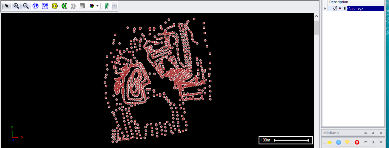
❖The spatial data will now be loaded into your graphics with the corresponding layer added.
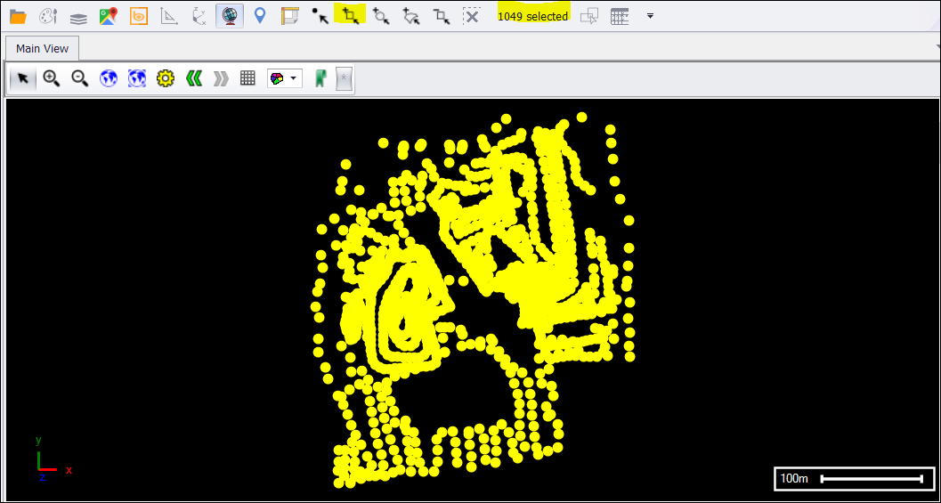
❖Select all your points with one of the selection tools.
❖To create a surface, click on From points in the Surfaces tab.

❖A window will come up. Click on Use scene projection.
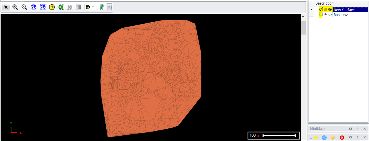
❖I ticked off the Base.xyz points layer so I can just see the surface that was created from the points. A new layer New Surface will also be added.
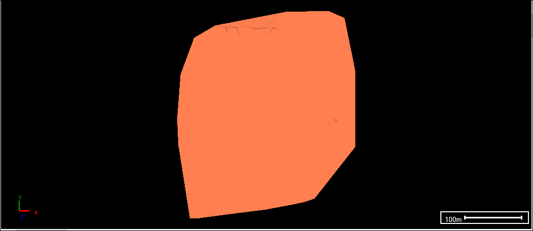
❖The current default scene renderer being used is GDIPlus. This causes the triangulated irregular network to be shown on your created surface and slower performance.
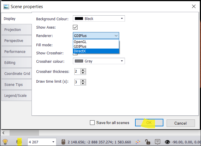
To change renderers to display a smooth surface and better performance, click on the globe per the screenshot below and select the Display tab. Then dropdown and choose DirectX – this is the best renderer to display 3D surfaces. Click on OK.
❖I renamed the New Surface layer to Base by double clicking on the layer.

❖I added another XYZ File and created a surface from the points per the same steps described above. I renamed this layer to Tops. (It is a stockpile surface that was created.)
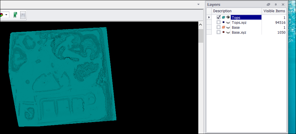
❖I ticked off the Tops.xyz points layer to just have the new surface Tops layer displaying. I also turned off the Base surface layer.
Note: To turn off the selection of the points in the Tops.xyz layer etc, click the X in the shortcut ribbon.
![]()
❖To rotate your surface (Tops) in space, first click on the Snap icon circled on the screenshot below which is at the bottom of the SurveyXL window. Then select Object – This needs to be set to ensure you are snapping on the object you are rotating. This allows the rotation about your data to be in view and seen correctly.
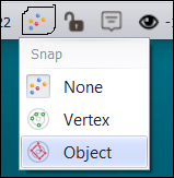
❖The Snap icon is now displayed differently when you have your snap on.

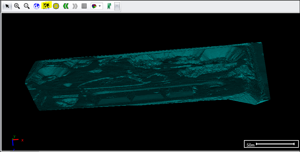
❖Your crosshair will look different when you are snapped to your object. To rotate, click and hold down the Ctrl key. Then at the same time hold down left click and drag about your scene. Your data will rotate accordingly.
❖Your data might now be out of the view plane. Just click Zoom fit to fix this.
❖To view your data from the top again, click the eye at the bottom of the screen and select Top.
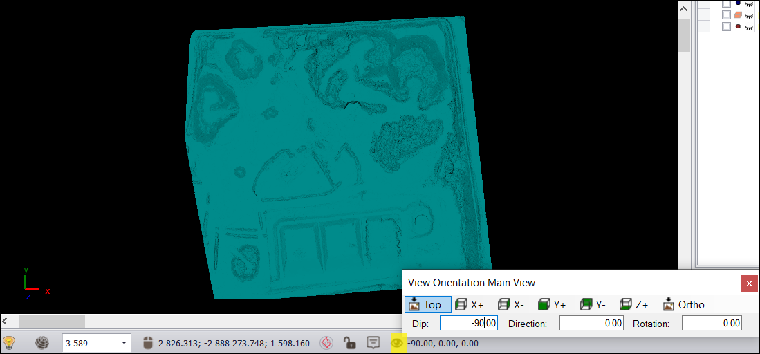
❖Turn on your Base surface layer now as well by ticking it on.
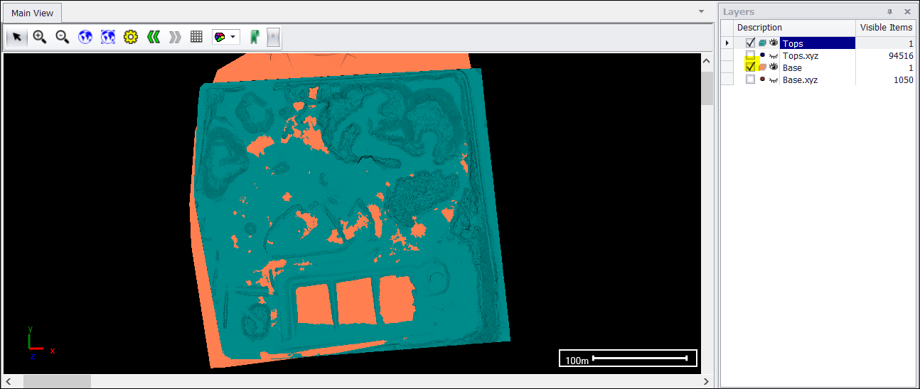
❖To do a Cut and Fill operation click on Cut and Fill from the Surfaces tab.

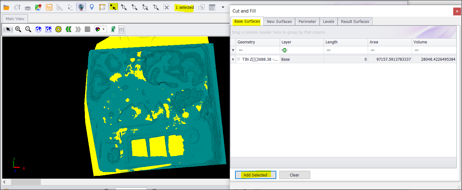
❖A Cut and Fill window will come up with the Base Surfaces tab selected first by default.
❖Select your Base surface layer by using the select by clicking tool. The selection will be yellow. Then click Add Selected. The data is then added into the Base Surfaces tab.
❖Go to your New Surfaces tab and select the Tops (stockpile) surface layer. (First deselect the Base surface layer.) Then click Add Selected. The data is then added into the New Surfaces tab.
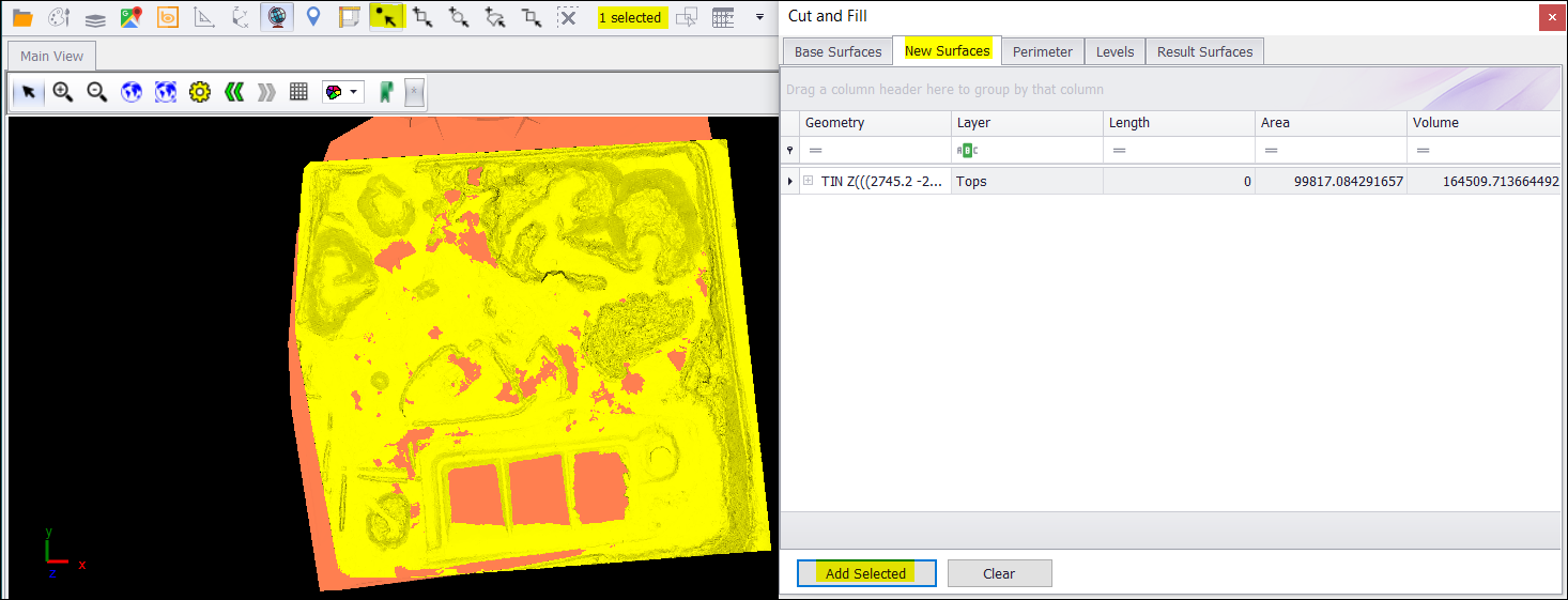
❖If one were wanting to do a Cut and Fill operation on specific perimeters within your layers, then you would go to the Perimeter tab.
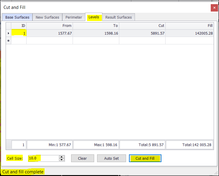
❖Go to your Levels tab. Cell Size by default is set at 10. Click on Cut and Fill to perform the operation on 1 level. The elevation From and To is populated, as well as the square meters for the Cut and Fill.
❖In the Result Surfaces tab, the Volume is populated for both your Cut and Fill.
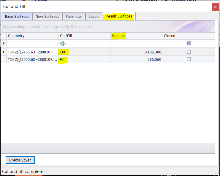
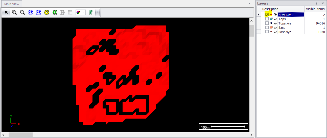
❖Click on Create Layer to view it in your graphics. A New Layer will be added.
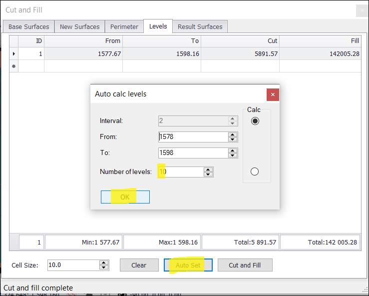
❖If you would like to perform the Cut and Fill operation on more than 1 level, go back to your Levels tab. Click on Auto Set, then choose your Number of levels. Click OK.
❖Now click on Cut and Fill.
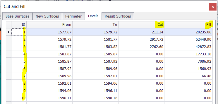
❖Your results are now on 10 levels.
❖You can also do contouring on your surfaces in SurveyXL. I will use the Tops surface layer in this example. Click on Contour/Section in the Surfaces tab.

❖Select your surface first using one of the selection tools.
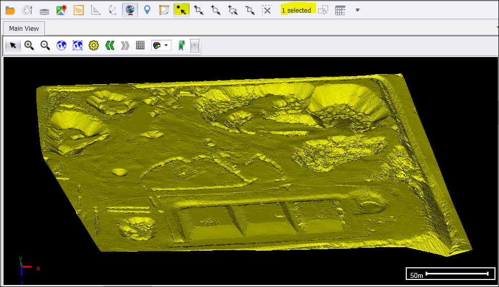
❖A Contouring/Section properties window will come up.
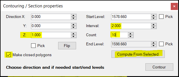
❖The Z direction by default is set at 1. I want my contouring to be closed polygons, so I ticked this on. Click on Compute From Selected which will automatically choose the Start and End Level. I chose Interval as 2 for each level of contouring and the Count 10.
There is also an option to pick your Direction and Start and End Level from graphics. Just tick the appropriate box and click on your scene one at a time to choose.
❖Now click Contour. You will be prompted on what projection to use for the new layer that will be created. Click on Use scene projection.
❖Contours/Sections layer will be added.
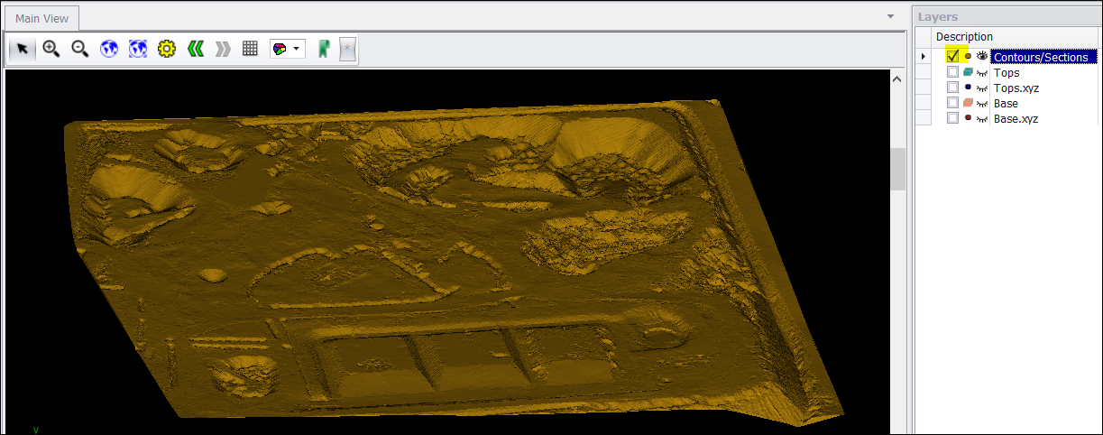
❖To see the exact contouring to identify catchment or drainage areas, I will set up a colour theme. This will also display in the Contours/Sections layer.
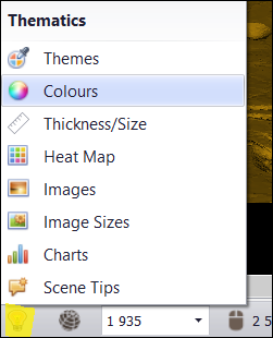
❖Click on the light bulb at the bottom left of the SurveyXL window and select Colours.
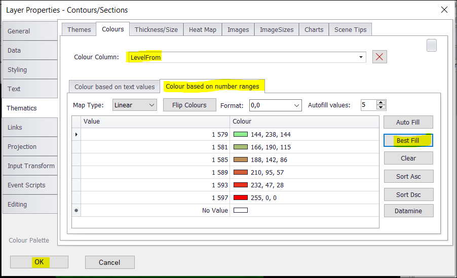
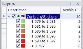
❖Select LevelFrom from the dropdown menu for your Colour Column. Select the Colour based on number ranges tab and click on Best Fill for your colours. The lowest contour level is green increasing to the highest level which is red. Click on OK.
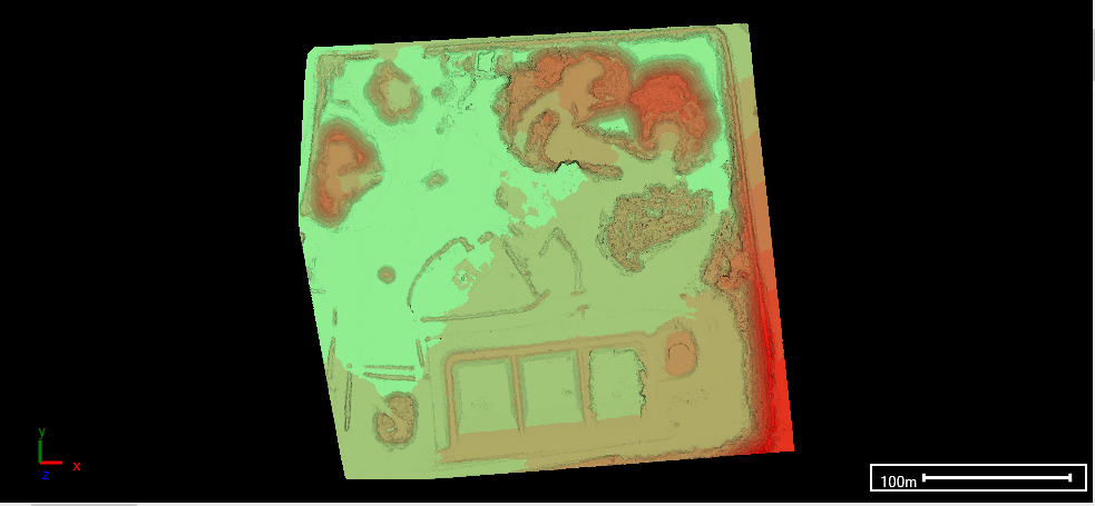
❖This view is actually upside down. Rotate the surface to the right side up and zoom in to see the contouring.
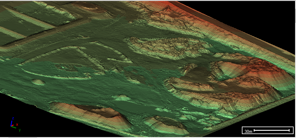
❖You can turn the various contour layers on and off for further analysis.

❖View your scene from the top again, click the eye at the bottom of the SurveyXL window, then click Top.
❖Now, you can also build a conceptual pit. To build it from the surface, click on the mouse location at the bottom of the SurveyXL window, then make your Z value 0 and click Set.
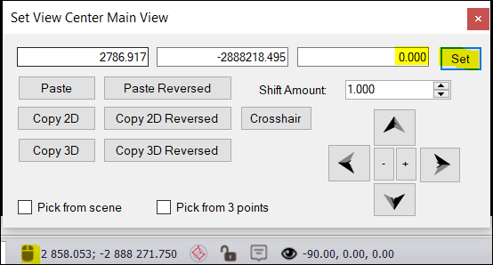
❖First, I will draw a pit outline. To do this, go to the Draw tab and select 3D Linestring.

❖Click once on your scene to start drawing, you will see a line being drawn. Click once again to draw it. Continue clicking in this way until you have your outline. To close the lines when you are done, click c on your keyboard.
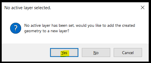
❖A window will then come up. Click on Yes to create a new layer.
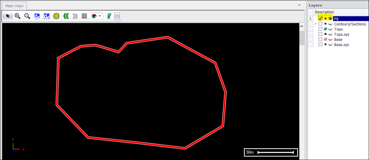
❖Your pit outline is now displayed on your scene. I renamed the new layer Pit.
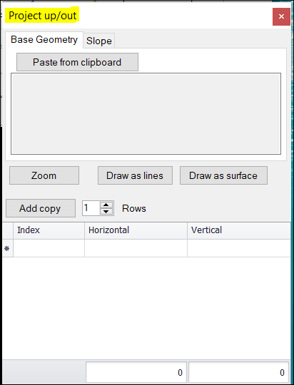
❖To create your actual pit now, go to your Utilities tab and select the Project Out operation.

❖A Project up/out window will come up.
❖Select your pit outline drawn using one of the selection tools.
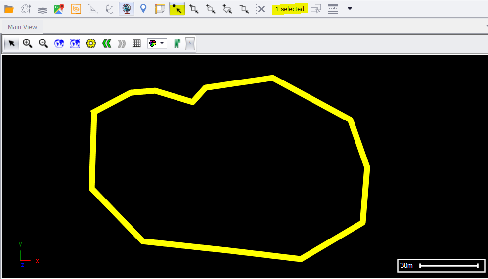
❖Go to your Edit tab, then select Copy Selected. (The geometry of the pit outline will be copied to clipboard.)

❖Go back to your Project up/out window and click on Paste from clipboard. The geometry will then be pasted.
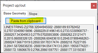
❖To start building your conceptual pit from the pit outline on the surface, type in 0 for Horizontal and Vertical.
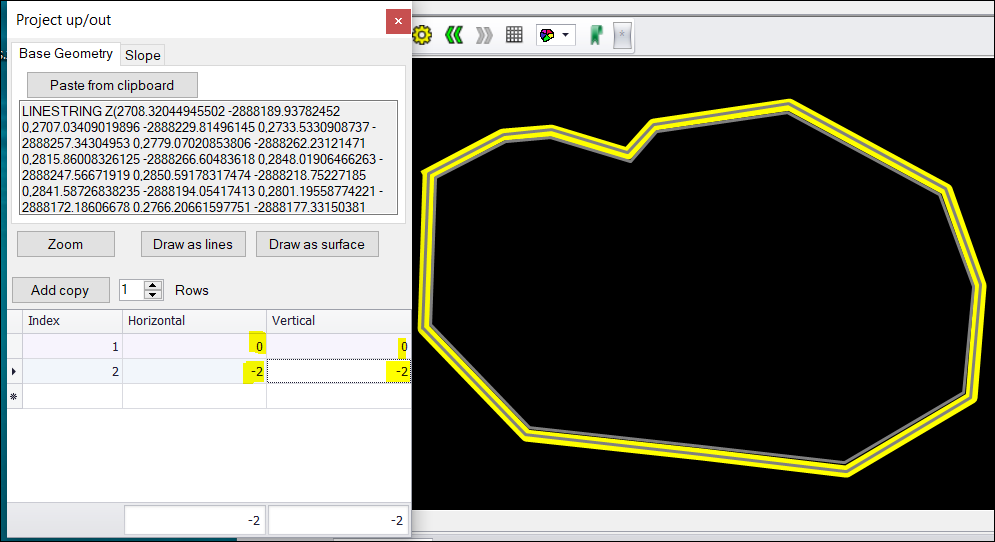
❖For the next ring, type in -2 for Horizontal and Vertical. This will make the ring inwards and downwards. The rings are drawn on the fly to your scene as you input the data.
❖To easily continue creating the rings to build your conceptual pit, click on Add copy as many times as needed.
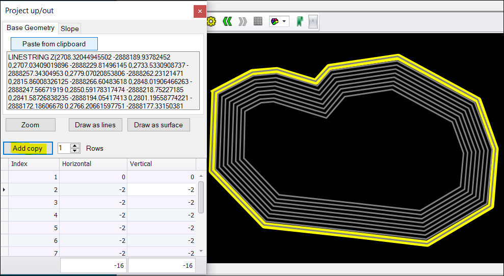
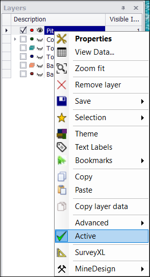
❖Your Pit layer is Active by default when it was created earlier. This means that while it is active, anything drawn on the scene will be added to this layer.
I want to create a separate layer when my pit surface is drawn, so right click on Pit, then click Active to take it off that mode.
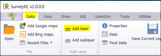
❖Create a new layer by going to your Data tab and selecting Add layer.
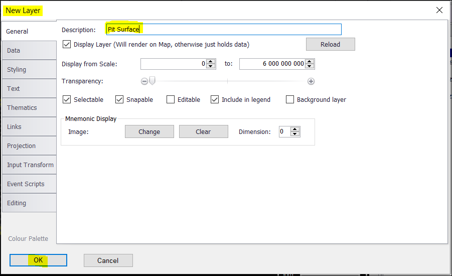
❖A New Layer window will come up. Rename the Description of the layer to your preference. I will use the default Styling - You can change it to your preference at any time.
❖Go to the Data tab. Click on Create to create the Geometry that will be added.

❖Click OK.
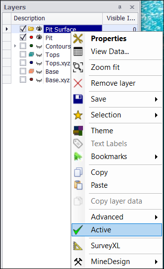
❖Pit Surface layer is now added. Make this layer active by right clicking on Pit Surface and selecting Active.
❖Now, click on Draw as surface in the Project up/out window. The surface data will be added to the Pit Surface layer and drawn on the scene accordingly. I rotated and zoomed to the surface to see it well.
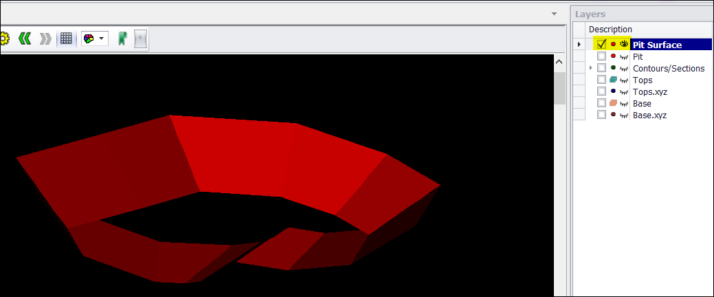
❖To close the Pit Surface, ensure it is first selected in graphics, then go to the Surfaces tab and select Close.


❖To get a volume now of this surface, you can use the Inspector tool in the shortcut ribbon. Click on it.
![]()
❖An ObjectProperties window will come up. You can now select your object.
❖Select your object by clicking on it on the scene or dragging a box around it to select it. Item Properties 1 of 1 window will show and your Layer: Pit Surface.
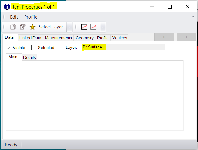
❖Select the tab Measurements to see all the measurements for the selected object which is the Pit Surface in this example.
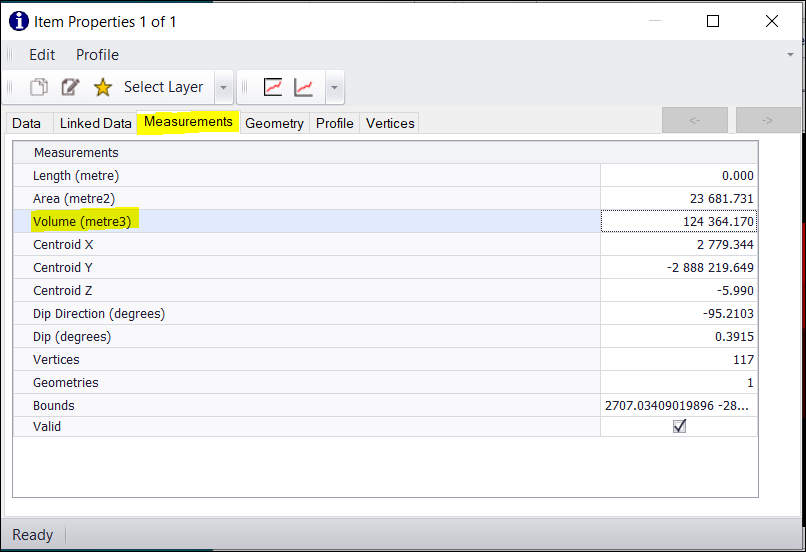
❖You will see the Volume (metre3) here.
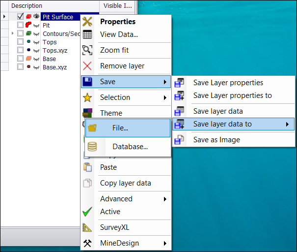
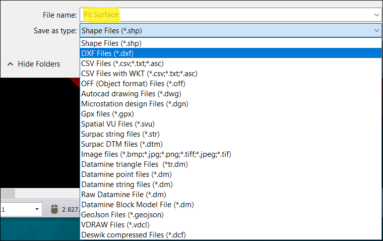
❖This surface can now be saved as a DXF File etc and shared with others. Right click on Pit Surface > Save > Save layer data to > File.
❖Currently, your scene is set to 1 view which is the Main View you will see if you go to your View tab.
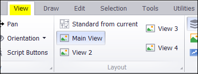
❖You might want to have more than 1 view for complex surveying. Click on View 2, View 3, and View 4 to see 4 different views of Pit Surface in this example. Each view works independently.
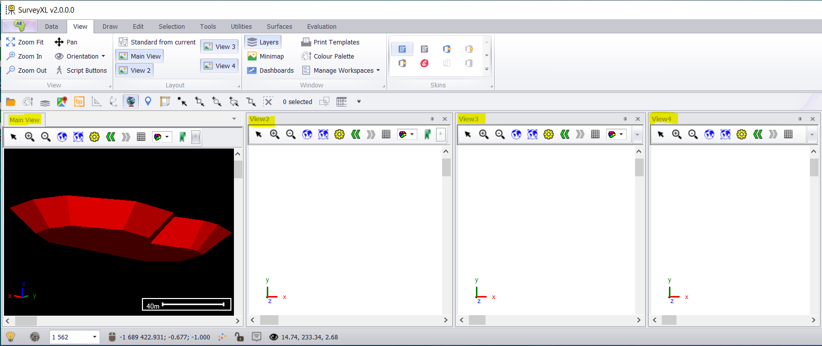
❖Set the view orientation of the Main View to the top so you can then see your other views in relation to it. Then select Standard from current in the View tab. Zoom Fit Layer to each view.

❖You now have your Main, Left, Front, and Orthographic views.
❖There are many other features in SurveyXL, but these are the main ones in this SurveyXL Basic Training Guide.