Project Out Tool Manual
❖The Project Out tool is a tool in all our spatial products that can be used to build certain kinds of surfaces like a pit or tunnel by projecting out from a base outline. It can be found in the following location:
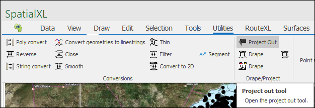
As a note, in order to use this tool you will need to be on a correct projection that enables working with 3D objects, there is a range of such projections to choose from but if you are not familiar with them a good default is World_Mercator:

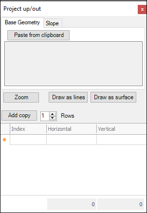
❖Clicking on it brings up the following dialogue box:
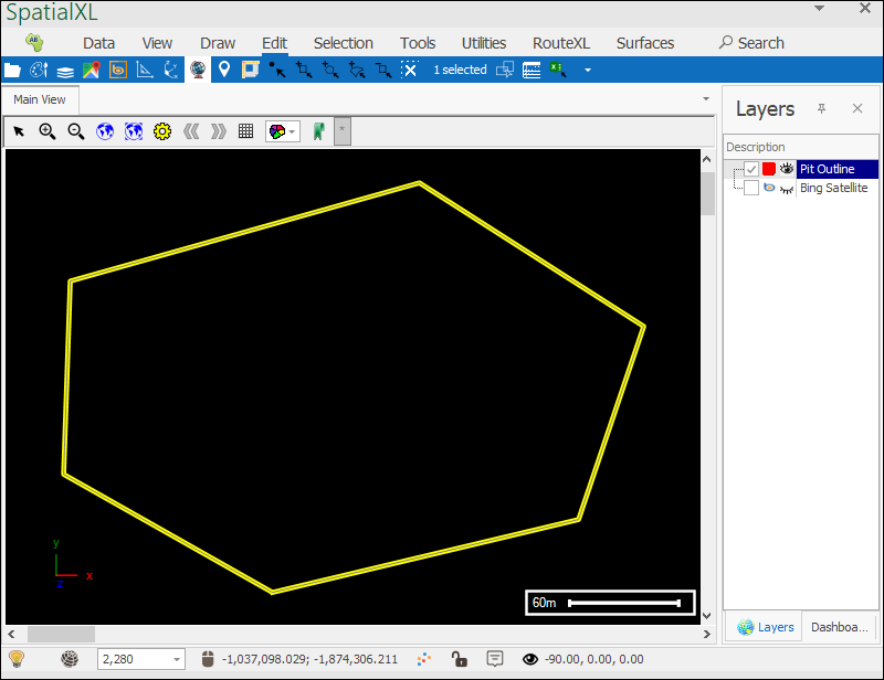
❖Before starting to use the tool, you would have an outline of the surface you plan to build as a layer in the Layers Description box:
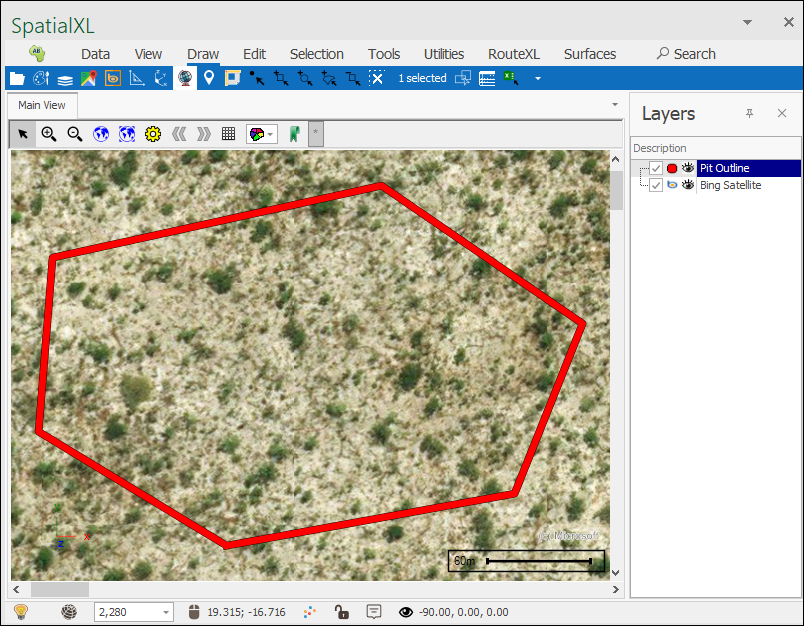
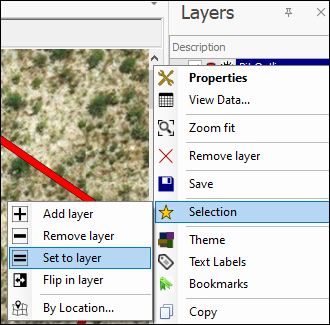
❖The next thing to do would be to select this outline either using one of the selection tools or right clicking the layer and choosing Selection>Set to Layer:
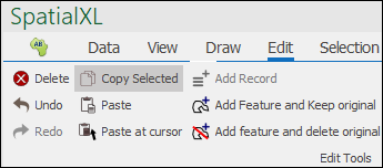
❖Now that the layer is selected you will need to copy it so you can paste its geometries into the tool, go into Edit tab and select Copy Selected:
❖If it is not already open, open the Project Out tool.
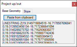
❖In the Base Geometry tab select Paste from clipboard, this will enter the geometries of your outline, which will be used to build the surface:
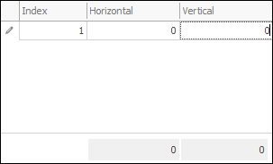
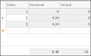
❖In the grid below enter in the dimension values for your surface, Horizontal and Vertical. In the first row enter 0 for both horizontal and vertical, this will ensure that the outline itself is included in the surface you will be creating:
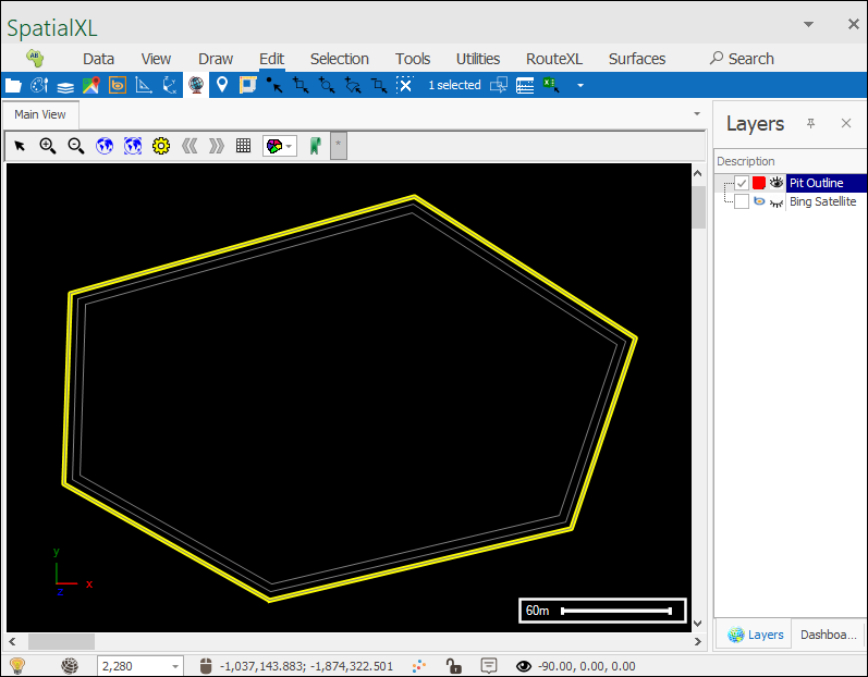
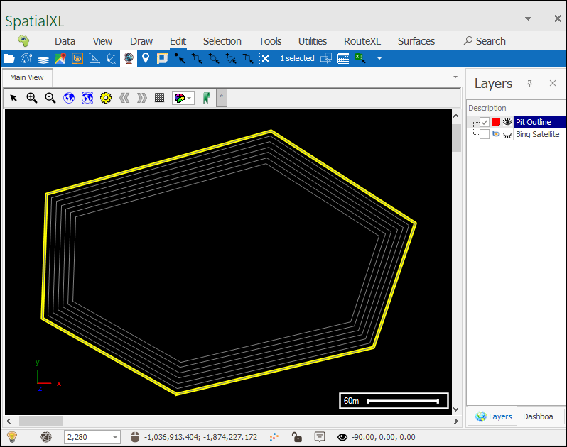
You will see that as you do this a grey outline is placed on your original outline, this is the first outline of your projected surface(I turned off the background map for the building of the surface so I can clearly see what is happening):
❖Then successively enter in the values for projecting out; each row represents a further projection out and as you enter these values in you will see grey outlines being drawn on the scene showing you how it is being projected:
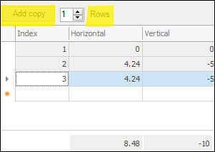
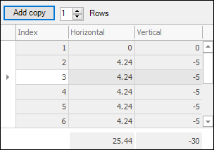
If you are just going to be repeating the same values as you project out you don’t have to keep entering them each time, you can use the Add copy button which will make a copy of whatever is in the current row you are on and you can further choose how many copies(rows) to put in by entering it in by Rows, each time the Add Copy button is selected a copy/copies are made:
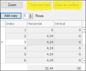
❖When you have projected out as desired and are ready to make the surface you can choose either to have it drawn as lines(Draw as lines) or as a surface(Draw as surface), the former will draw it just as it looks now, as a series of outlines or if you choose the latter it will make the outlines into a surface:
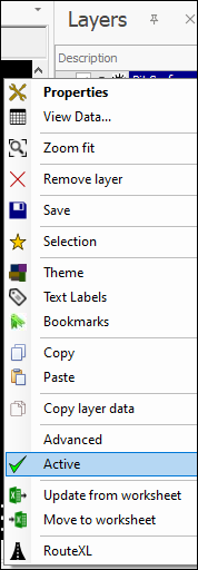
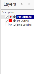
The tool draws the surface to an active layer so you will need to have one ready in your Layers Description box, to make a layer active right click on it and select Active, the layer will then be in bold letters showing that it is active meaning that whatever drawing operation is done it will be drawn to that layer:
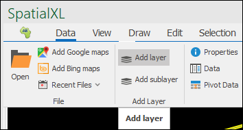
If you do not already have a layer to draw to you can create one by going to the Data tab, then selecting Add Layer:
❖With your active layer now ready you can select the Draw as lines or Draw as surface button.
❖Your surface has been created:
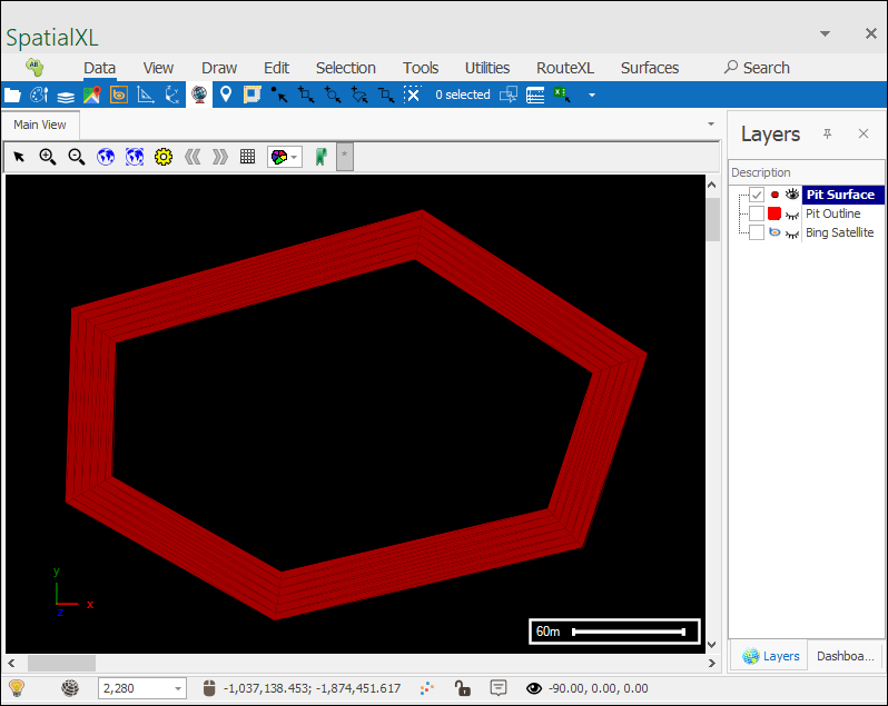
The grey outlines that you saw when busy using the tool will disappear once you exit the tool as they were just temporary outlines to show how the surface was being projected out.
❖You can now select one of the Snap tools to snap to the surface. Then hold down ctrl and click in the scene on the surface and drag to move your surface around and inspect it:

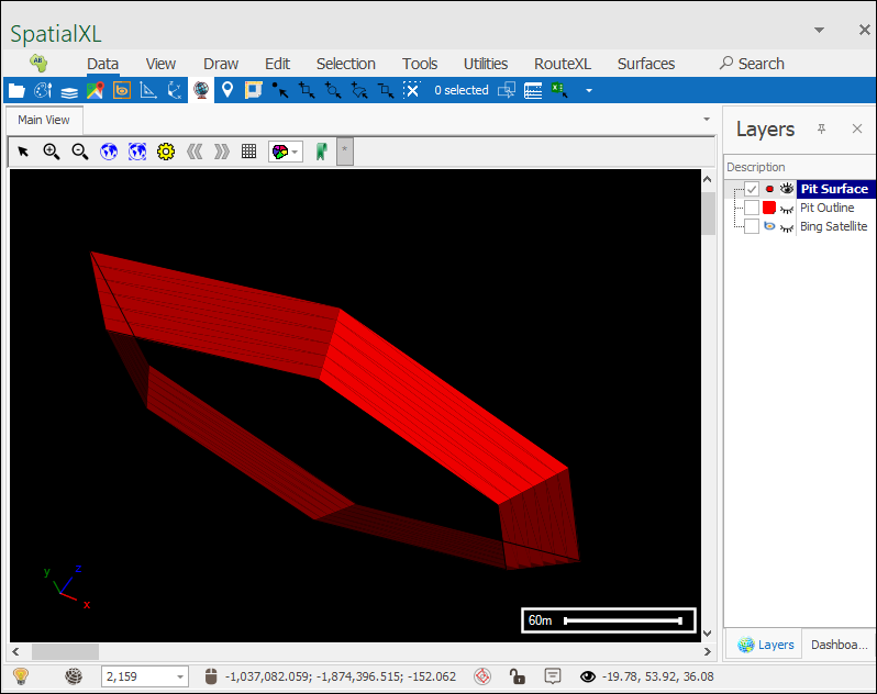
❖Now you can inspect this surface using a tool like the Inspector:
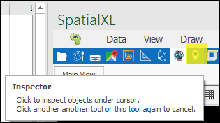
However with the surface in its current state you wouldn’t be able to get a volume for it so what you can do is select the surface using one of the selection tools then close the surface using the Close tool in the Surfaces tab:
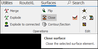
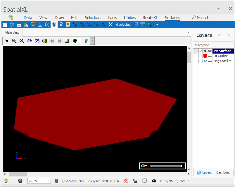
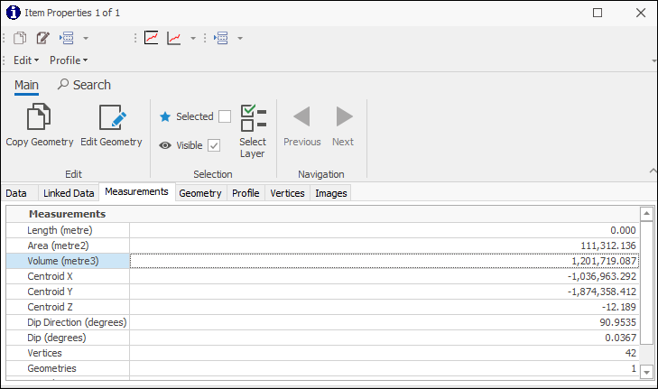
The surface is now closed, and you can get a volume for it using the Inspector tool, just click on the surface in the scene and the information for it will populate in the Inspector dialogue:
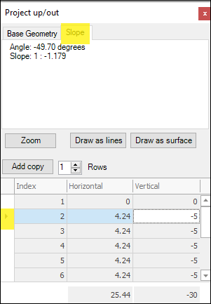
❖What you can also make use of when using the tool is the Slope tab, simply select a row or rows in the grid below and the total slope and angle of these rows will be displayed:
