Excavation Instructions Manual
❖Excavation Instructions is a tool available in all our spatial products that allows you to generate instructions for an excavation between two linestring borders relative to a working line. It is found in the Draw tab(1)(2):

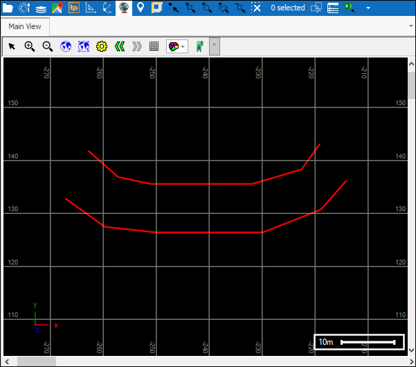
❖Before using this tool you would have your linestring borders for the excavation:
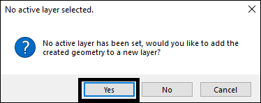
❖Click on the tool to open, if you don’t already have an active layer then it will ask you to create a new layer for the instructions to be drawn to, click Yes:
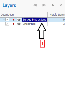
A Survey Instructions layer(1) is created for you and the following dialogue will come up(2):
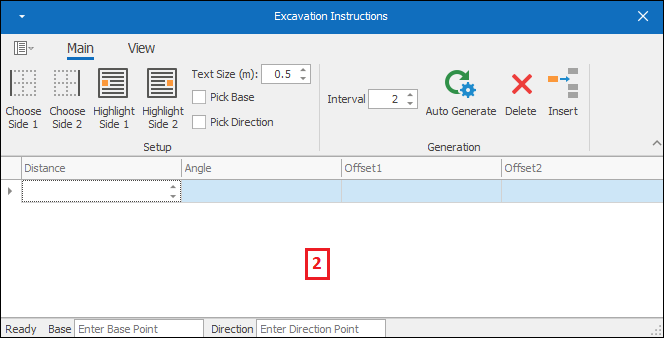
❖The first thing to do is to choose the sides of your excavation. Select the first side in your scene(1) and then click the Choose Side 1 button(2):
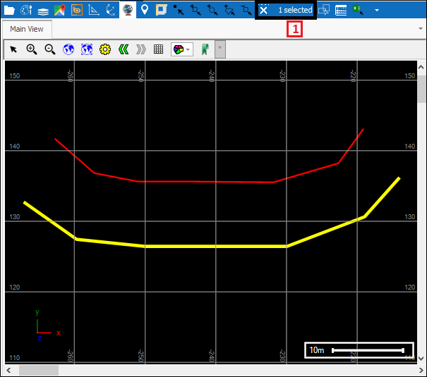
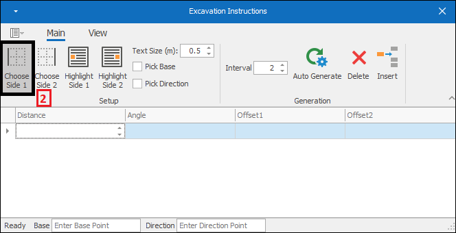
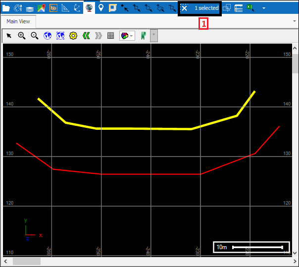
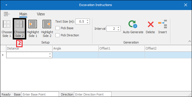
❖Next you choose the second side by selecting in your scene(1) and then clicking the Choose Side 2 button(2):
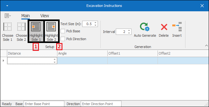
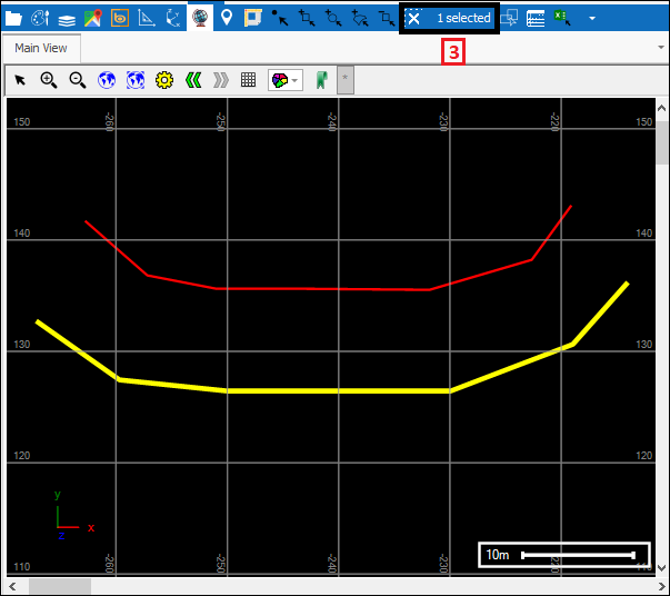
❖You can confirm and see which side is side 1 and side 2 by clicking the Highlight Side 1 button(1) and Highlight Side 2 button(2) which will highlight the side in your scene(3). You can unhighlight it by clicking the button again:
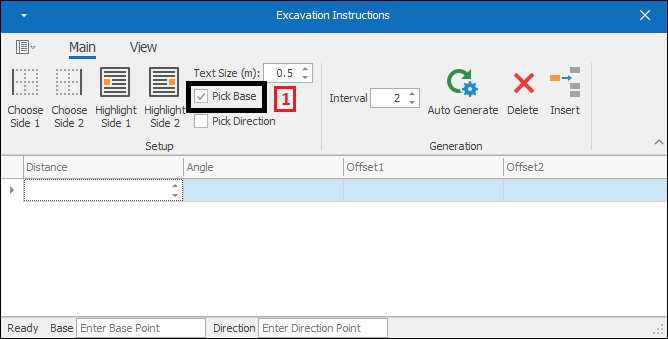
❖The next thing to do is to pick the base peg or point in your scene. Tick on Pick Base(1) and then click in your scene at the point(2), this will then warn you that your direction has not been set up(3), click OK, and then tick on Pick Direction(4) and then choose the direction from the base point by clicking in your scene(5). The values are populated in the boxes below(6):
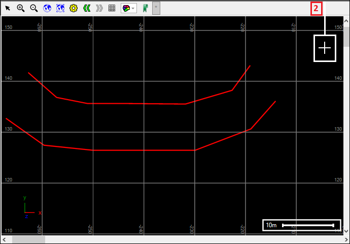
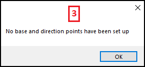
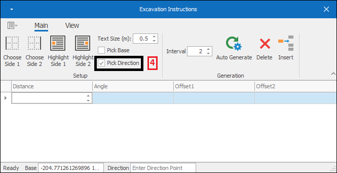
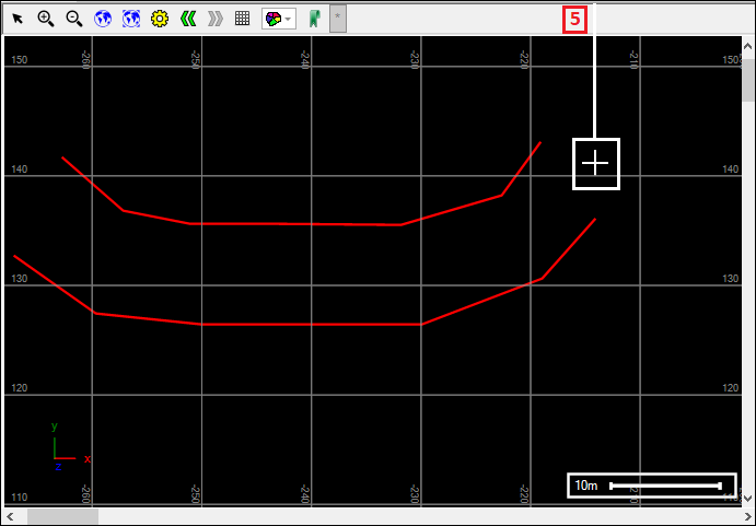
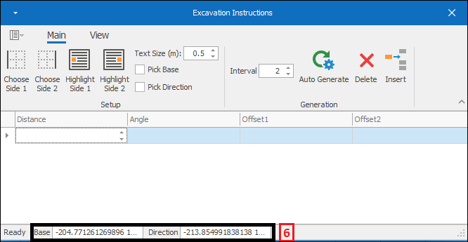
❖Choose the text size for the text that will be displayed by the line that will be going through your excavation by Text Size(m) :
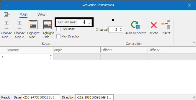
❖Now, in the grid below you can type in the Distance and Angle(0) for the line that will be going through your excavation. The Offset1 and Offset2(1) will automatically populate as your line is drawn, being the offset of the line from each side of the excavation; in my example I will put my Distance as 10 metres and leave my Angle at 0(2), as I do this I see the first part of my line appear on the scene(3) :
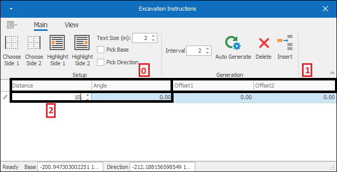
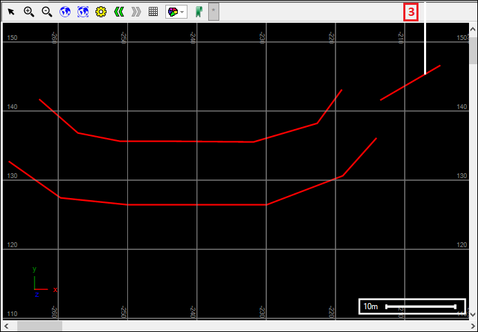
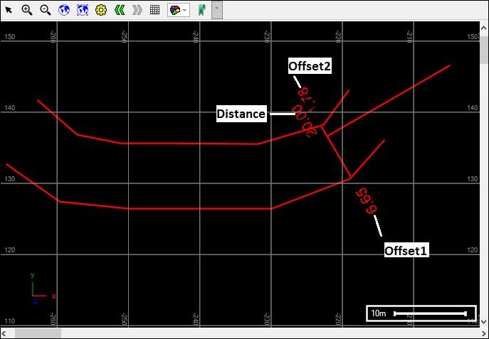
Now I will add another row in the grid to make the next part of the line and as you will see when the line goes into my excavation the different values are now displayed beside it:
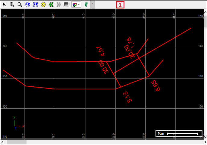
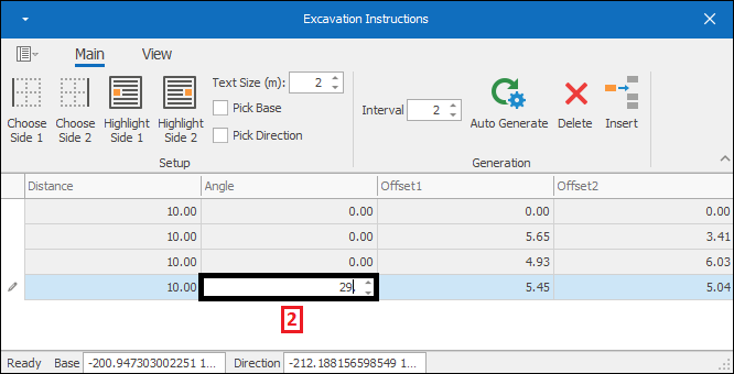
❖I will add another row in my grid and as you will see the line now needs to turn in order to follow the shape of the excavation(1) so the next row I enter in I’ll change the angle to follow the shape(2):
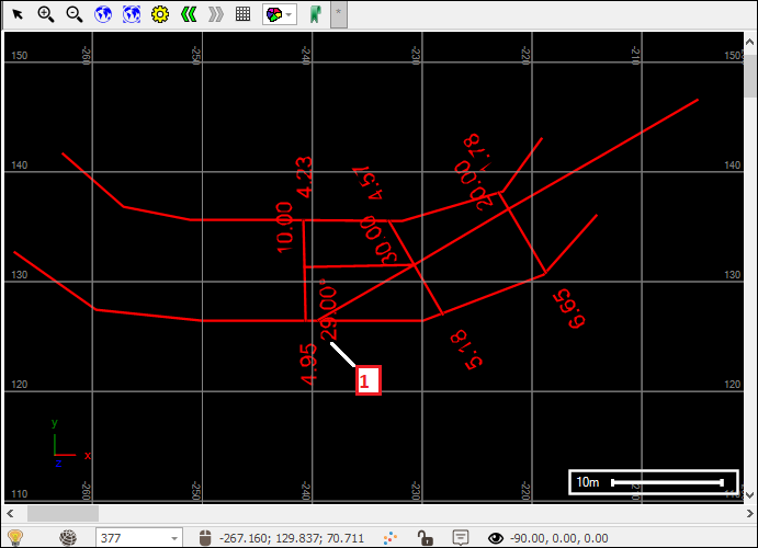
And as you can see the next part of the line changes angle and follows the excavation and an angle value displays as well at this point(1):
❖I will enter in more rows and change angles as needed until my line has gone all the way through my excavation:
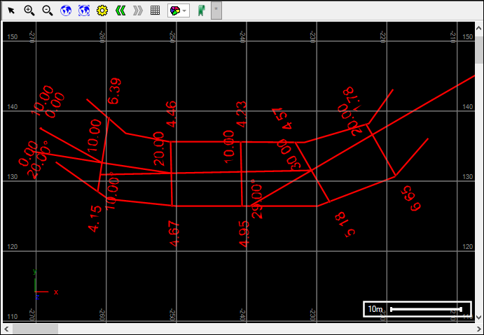
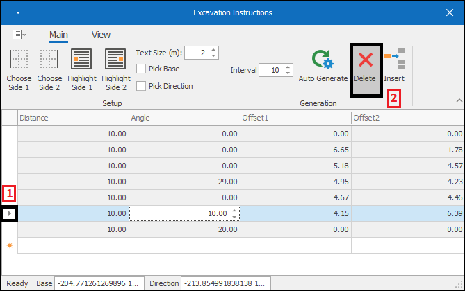
❖If you want to delete a row (and therefore part of the line drawn) simply select the row(1) and then click the Delete button(2):
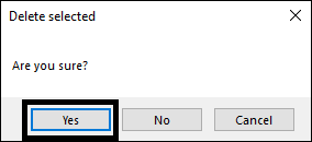
The following message will come up click Yes:
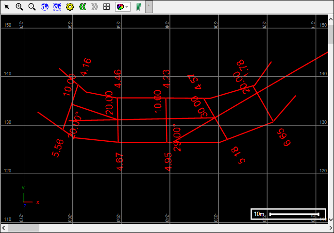
And your row has been deleted and the line will shift accordingly in your scene:
❖At Interval(1) is a default distance setting you can set for each new row that gets made in the grid. Now if I were to insert a row by using the Insert(2) button a row will be added with that distance and it will be added right before the current position in the grid:
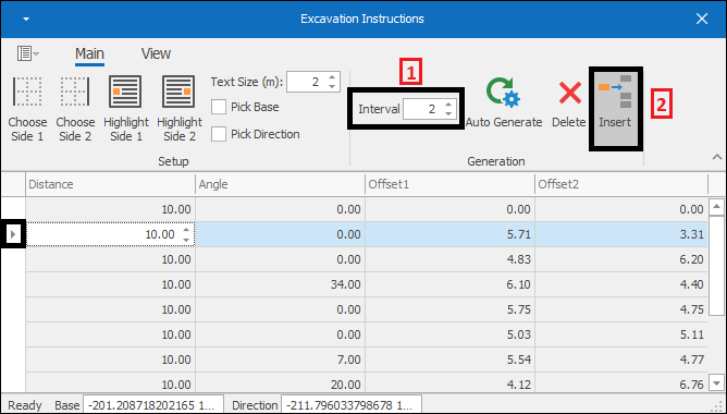
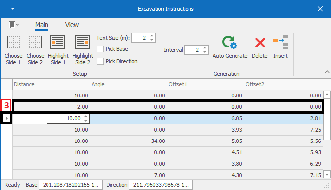
Your line will of course shift accordingly once the new row is added.
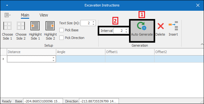
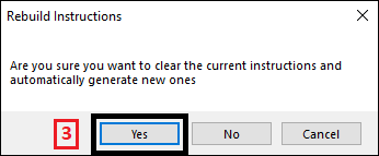
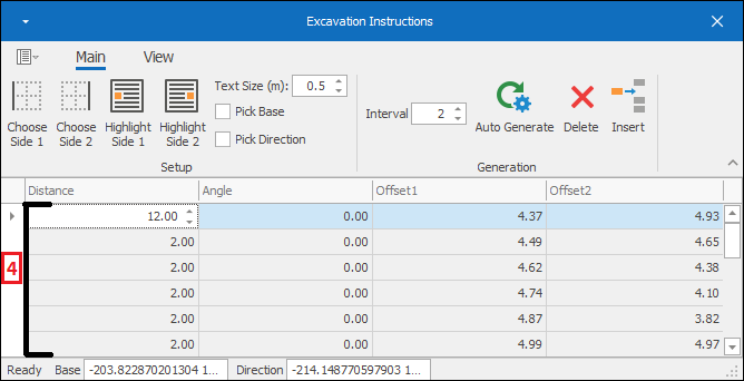
❖What you can also do is instead of manually entering in rows is use the Auto Generate(1) button which will auto generate instructions using the interval specified(2). The following message will come up and just click Yes(3) and your instructions will be auto generated(4):
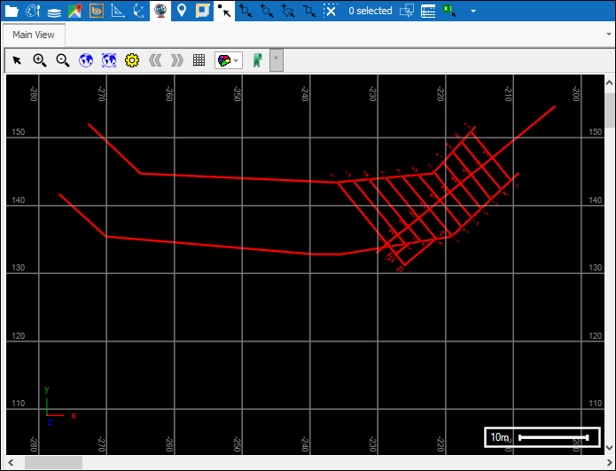
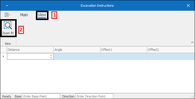
❖If you are zoomed or moved away from your excavation or you just want to fit it to your screen perfectly you can at any time go to the View(1) tab and zoom fit to it using the Zoom fit(2) button:
